Styx-on-a-Brick
Chris Locke
chris@vitanuova.com
Vita Nuova
June 2000
Background
The aim of the Vita-Nuova ‘‘styx-on-a-brick’’ project was to demonstrate the simplicity of the Styx protocol and the ease with which a Styx ‘stub’ can be implemented on tiny devices. We also aimed to demonstrate the effectiveness of a protocol based approach to resource management and sharing, whether the resource be a physical device or a software service.
Adopting a protocol-centric view of resource and service management, as opposed to a language-centric approach (as emphasised for instance by Jini™ with Java) greatly eased the software burden on our tiny target device - implementing a simple protocol in firmware required much less work than trying to implement a virtual machine. We are confident that if we had adopted a language-centric approach, we would not have completed the project within our aggressive space and implementation time constraints.†
The project took 2 weeks from start to finish. In this time the firmware was developed and all client software was written: firmware download, IR-link protocol support, clockface application and worldclock application. Two people worked on the project, one full-time, the other (Nigel Roles) part-time.
The demo was then taken on a Press Conference tour of the US and later appeared at the Usenix2000 Plan 9/Inferno BOF at the request of Dennis Ritchie.
I should stress that the project was a demonstration of the ease of supporting Styx on small devices - it was not a demo of robotics! (Indeed, the design of the IR-link protocol, Styx name space and the services provided by the firmware would be considerably different for serious robotics.)
The project used a standard Lego™ Mindstorms™ robotics kit - the ‘‘Robotics Invention System’’. This consists of the RCX brick, 2 motors, 2 button sensors, a light sensor and a whole load of lego pieces - including wheels, gears and axles; which all adds up to a whole load of fun!
The RCX brick is an Hitachi H8 microcontroller with 32K of RAM and a 16K ROM BIOS. The RCX provides 3 motor outputs and 3 sensor inputs. Communication with the RCX is via IR. An IR tower is supplied with the ‘‘Robotics Invention System’’ that connects to a PC via a serial port.
Acknowledgements
Before going any further I must acknowledge the work of Kekoa Proudfoot at Stanford and Russ Nelson at Crynwr Software. Without their valiant efforts we would not have been able to pursue this project. Our work relied on the documents and librcx suite provided by Kekoa:
http://graphics.stanford.edu/~kekoa/rcx/
and on information from Russ Nelson’s web site
http://www.crynwr.com/lego-robotics/
Files
The files in the legostyx.tar file are shown in Table 1.
Project details
1. Firmware Download
The RCX brick comes supplied with Lego firmware to be downloaded into the RAM via the IR link. The ROM implements a monitor which provides for the firmware download, as well as other ’op-codes’.
We wrote our own firmware in C using the GNU H8 compiler suite on a FreeBSD machine. The code used Kekoa’s librcx library for interfacing to the RCX ROM routines. (We should have liked to have done an H8 code generator for our own compiler suite, but time did not permit this!) The gnuh8 list is accessible via:
http://www.pcserv.demon.co.uk/
First up we had to write a Limbo application to communicate with the ROM, via the IR tower in order that we could get our firmware downloaded onto the RCX. This is the firmdl application. Source files: firmdl.b, rcxsend.b and timers.b
2. Styx Comms Link
Having got a means of installing our firmware we needed a means of delivering Styx messages to and from the Brick.
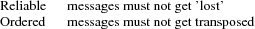
Styx makes certain demands of its transport media:
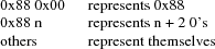
The RCX ROM provides a couple of functions for IR comms - a routine to check for message reception and a routine for message delivery. The message reception routine receives the data of a RCX "Transfer Data" message (RCX op-code 0x45)
We chose to use this facility as a means of delivering Styx messages to our Firmware on the Brick. But it did not provide the Transport properties that Styx requires. To meet the Styx requirements we implemented a simple ’alternating bit’ protocol whose payload was the Styx messages themselves. These Link protocol messages become the payload of the RCX "Transfer Data" messages.
The IR link is very slow, the baud rate of the IR tower serial link is 2400 and the ROM message format requires that every byte of a message be doubled up with its complement. (e.g. the byte 0x7e is transmitted as 0x7e, 0x81) This is because of the simple way that the RCX ROM and hardware handle elimination of the ambient IR signal level - all message have the same number of 1s and 0s so the ambient IR level can be negated by subtracting the average level. All RCX messages are also prefixed by a header and suffixed with a checksum:
0x55 0xff 0x00 D1 ~D1 D2 ~D2 ... Dn ~Dn C ~C
where D1 ... Dn are the bytes in the message body and C = D1+D2+ ... Dn.
Therefore, the effective data rate is considerably less than 1200 baud.
We noted that many Styx messages, especially Twstat and Rstat, contained a high proportion of 0 byte values.†
Consequently, we decided to incorporate a 0-run-length compression scheme in our simple link protocol.
Within the payload of the link messages:
An additional burden is that communication with the Brick via the IR tower has to be strictly synchronous. The IR tower echoes back all data transmitted to it on the serial link as well as any data received on the IR link. Therefore the brick must not send IR data while the PC is sending serial data to the tower. In order to achieve this a ’ping-pong’ communication scheme must be employed. The PC is the master, the brick is the slave. The master sends a request and waits for the reply from the slave. Only the master is allowed to start an exchange.
The problem with the master/slave style of communication is that a Styx Server implements blocking requests, e.g. reads and writes, by simply not responding to the request until the operation is completed. This does not fit with the link protocol requirement that the server (slave) always respond and the requirement that the brick cannot instigate a data exchange. The firmware could simply reply with an empty Link protocol message but it then has no way of giving timely notification of the completion of a pending Styx request as it is not allowed to start a link-protocol message exchange.
To get around the pending Styx reply problem, the link protocol header incorporates a flag that the slave (brick) can set to indicate that it is holding outstanding requests and that the master (PC) should continue to poll the slave in order to receive their replies in a timely fashion.
The link protocol message format is as follows. Request from Master (PC) to Slave (RCX):
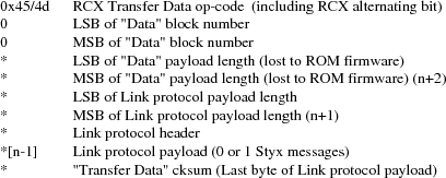
Note that the 0x45 ROM op-code ("Transfer Data") message incorporates a checksum byte at the end, but the ROM doesn’t bother to check it so we moved the last byte of the Link protocol payload (or the link header if the payload is empty) into the checksum position of the ROM message.
Reply from Slave to Master:

The Link protocol header has the following flags:
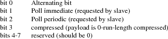
The master flips the Alternating bit for every message that it successfully delivers. If a slave reply is lost or corrupted the master will re-send the message using the same alternating bit value. The slave should not act on a repeated message but should re-send it’s last response. The value of the alternating bit in the slave response is the same as in the request from the master.
The Poll immediate bit indicates that the slave has more data to send to the master. The master should immediately send another Link-protocol message, even if it has no data to send, so as the slave can reply with its pending data.
The Poll periodic bit indicates that the slave has pending (blocked) requests that it will reply to sometime in the future. The master should periodically poll the slave, even if the master has no data to send. The polling period should be small enough that reply latencies are acceptable.
3. The name space
We now have a means of getting Styx messages to and from the brick. But what does the name space provided by the firmware on the brick look like?
We wanted a generic name space; one that reflected the functions of the brick, not the model attached to it, so that the same firmware could be used with many different robots.
The brick has 3 motor outputs and 3 sensor inputs. The motors can be run forwards or reverse with 8 different power settings. They can be stalled, also with 8 power levels, and they can be left ’floating’ [A stalled motor presents resistance to turning proportional to the stall power level]
There are 2 types of sensor - buttons and light-sensors. [You can also get a ’rotation sensor’, but we had not got one in our kit!]
We decided on a name space comprised of 2 directories, motor and sensor. We didn’t need to use subdirectories for our name space but it was easy, so we did!
The motor directory contains 4 files - 0, 1, 2 and 012. The files 0, 1 and 2 represent the individual motor outputs and accept command messages of the form ’XP’ where X is a direction and P is the power level.
X can be one of

P is a digit in the range ’0..7’
The file 012 takes messages of the form ’XPXPXP’ enabling the state of all the motors to be modified with a single message. The first XP pair affects motor 0, the middle pair affects motor 1 and the last pair affects motor 2. XP can be ’--’ indicating that the state should remain the same as before.
The sensor directory contains three files 0, 1 and 2, corresponding to the three sensor inputs on the brick.
Before a sensor file can be read it must be configured by writing a configuration message to the file. These message take the form ’Tv*’ where T is the sensor type and v* is a threshold value. The idea of the threshold value is that reads of the sensor file wil block until the threshold value has been achieved.
Reads of a sensor file return its current value. When a sensor file is configured any pending reads of the sensor are failed with the error message ’reset’.
The available sensor types are:

The threshold value for a button sensor is a click count. So the control message ’b0’ configures a sensor to be a button and subsequent reads of the file will yield the current click count.
The message ’b20’ will cause subsequent reads to block until the click count reaches 20 or more.
The threshold value for a light sensor is a raw sensor value qualified by ’<’ or ’>’.
The control message ’l>600’ configures the input to be a light sensor and subsequent reads will block until the sensor value exceeds 600. If the ’<’ qualifier is used, reads block until the value drops below the threshold.
Using the Styx firmware
4. Download the firmware
Use the firmdl command to download the firmware to the brick
% firmdl 0 styx.srec
%
The first argument is the number of the inferno serial port ( /dev/eia0 in this example). The second argument is the file containing the firmware image in s-record format.
The firmdl app prints the response code from the ROM. On successful download the ROM reports:
Just a bit off the block!
Once the firmware is downloaded it is immediately run. The RCX display should be showing the ’running man’ symbol. If at any time the Styx firmware encounters an error, the ’running man’ is changed to a ’standing man’ and the source code line number of the error is displayed on the LCD. The firmware doesn’t stay resident: it monitors the on/off button and restarts the ROM monitor when it is pressed.
5. Start the link protocol
% legolink 0
%
The legolink argument is the serial port over which to run the link protocol. This will be the same as the first argument to the firmdl command.
Once started the legolink command creates the file /net/legolink in the Inferno name space. Any reads/writes of this file are the payload data of the link protocol.
6. Mount the brick name space
% mount -o -A /net/legolink /n/remote
The -A flag to mount prevents the command from trying to do authentication on the link before running the Styx protocol over it. The -o option uses an older version of Styx. The second argument to mount is the the file over which the Styx protocol will be run. Raw Styx messages are written to and read from this file. The third argument is the directory on which to mount the name space presented by the Styx server on the other end of the link - the firmware on the Brick.
7. Explore the name space
% cd /n/remote
% ls
motor
sensor
% ls motor
motor/0
motor/1
motor/2
motor/012
% ls sensor
sensor/0
sensor/1
sensor/2
%
Attach a motor to the first output and a button sensor to the first input and then try the following...
Start motor...
% cd motor
% echo -n f7 > 0
%
Reverse the motor...
% echo -n r7 > 0
%
Stop the motor (float)...
% echo -n F0 > 0
%
Notice the need for the -n flag to echo. The firmware is a bit touchy about the format of the motor control messages - they have to be 2 bytes long.
Run the motor for (a little more than) 5 seconds...
% echo -n r7 > 0; sleep 5; echo -n F0 > 0
%
It takes time on the slow link to open the file for the control message to stop the motor. It should be possible to reduce the delay by keeping the file open:
% {echo -n r7; sleep 5; echo -n F0} > 0
%
but the firmware only accepts command messages written to file offset 0.
[Fixing this is left as an exercise for the reader!]
Ok, lets play with a sensor...
% cd /n/remote/sensor
% echo b0 > 0
% cat 0
0%
Note that the sensor file isn’t as fussy about its message format as the motor file.
Click the button a few times and then try reading the sensor file again
% cat 0
4%
Let’s try a blocking read on the sensor
% echo b5 > 0
% cat 0
[click the button 5 times]
5%
Ok, we’re done playing - unmount the brick name space
% cd
% ls /n/remote
/n/remote/motor
/n/remote/sensor
% unmount /n/remote
% ls /n/remote
%
The Clockface robot
So we have a means of controlling the brick via Styx. We now needed to design a robot suitable for demonstrating the software.
The robot needed to be static; the IR link needs to maintain line-of-sight contact between the IR tower and the brick. The operation of the robot needed to be clearly visible to a group of people in a conference room. We also wanted a robot that we could layer services on top of each other to demonstrate the versatility of Inferno name spaces.
We decided on a clock robot. The robot is static; it doesn’t move around the room! The clockface would be visible and its operation obvious to a group of people in a reasonably large room.
The clockface robot also allowed us to layer services:
Initially we just mount the Brick name space. This name space represents the services of the brick - nothing is known of the robot model that is attached to the brick.
We then start the clockface service. This knows how to use the name space of the brick to control the motors and sensors of the clockface model. The clockface service provides a clockface file which accepts time values (e.g. ’14:35’), the service then runs motors and reads sensors to set the hands of the robot to the specified time.
On top of the clockface service we can run a world-clock service. This periodically reads the system clock and writes time messages to the clockface file resented by the clockface service. The world-clock service also provides a configuration file so that the user can set the time zone of the clock display. Writing a time zone abbreviation into the control file causes the world-clock service to write new time messages into the clockface file to reflect the new time zone setting.
By using Inferno’s ability to export a name space, any of the clock services could be running anywhere in the network. The Lego brick could be attached to machine A. Machine B could be running the legolink application using /dev/eia0 imported from machine A. Machine C could mount the /net/legolink file imported from machine B’s name space. Machine D could then run the clockface service over the brick’s name space imported from machine C, etc. etc.
The source of the clockface service is clockface.b.
The source of the world-clock service is worldclock.b.
Final Notes
The firmware could do with some more work on it, such as the overly strict length restriction on motor control messages, or the fact that control messages must be written at offset 0.
Please feel free to fix problems and make modifications. I am more than happy to discuss the software and answer any questions you may have.
Have Fun!
.KD 120 0
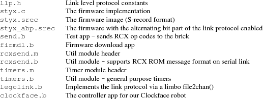
Table 1. Files in the Styx-on-a-Brick package